Integrating storage silos with a concrete batching plant requires more than connecting pipes and conveyors. It demands coordinated design, accurate material flow, and disciplined commissioning. This guide explains How to integrate silos with concrete batching plants through practical engineering considerations. Cement, fly ash, and mineral powder must reach the weighing system steadily, without bridging or sudden surges. Small details matter.
An experienced plant engineer will check silo capacity, outlet geometry, screw conveyor size, weighing accuracy, and dust-collection performance. A typical installation may include a 100-ton cement silo, a horizontal screw conveyor, pressure relief valves, level sensors, and a pulse-jet filter. Each component must work with the plant’s control system. The PLC should prevent overfilling and stop feeding when a weighing error appears.
Site conditions also shape the final solution. Uneven foundations, humid weather, limited access, and frequent truck deliveries can change the design. Chinese batching plant manufacturers often provide integrated layouts, but buyers should verify drawings, material compatibility, service support, and testing records. Claims alone are not enough. Ask for evidence.
Safety procedures deserve equal attention. Proper grounding, guarded moving parts, inspection platforms, and controlled dust emissions protect workers and equipment. Local technical requirements still apply. A design that works in one region may need adjustment elsewhere.
Some projects expose an uncomfortable truth: the cheapest integration may create higher maintenance costs later. Poor calibration, weak filters, or undersized conveyors can interrupt production. Engineers should review these weaknesses honestly before installation. Reliable integration is not a single product. It is a measured process that connects storage, dosing, control, and daily operation.
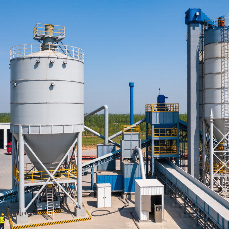
In concrete production, a silo is a vertical storage vessel for cement, fly ash, or other powdered materials. It protects these materials from moisture, contamination, and unnecessary handling. It keeps powders dry. A batching plant measures and combines cement, aggregates, water, and admixtures to produce controlled concrete batches. Its main equipment includes aggregate bins, weighing hoppers, conveyors, a mixer, and an operating system.
Silos and batching plants work together through screw conveyors, pneumatic lines, level sensors, and dust filters. The silo releases powder only when the batching system requests it. Accurate weighing is essential because small cement errors can affect strength and workability.
On a busy construction site, clear material flow reduces waiting time and prevents cross-contamination. Dust control matters. Sealed connections and regular filter cleaning support safer, cleaner operation.
Practical integration requires more than placing a silo beside the plant. Engineers should check foundation loads, access for tanker delivery, cable routing, emergency stops, and maintenance space. Moisture sensors may also improve aggregate correction during wet weather.
Experienced operators know that calibration can drift after repeated production. The design is rarely perfect. A sensible system leaves room for inspection, adjustment, and future capacity changes. Reliable records of weighing, cleaning, and repairs also help technicians identify problems before production quality declines.
Integrating Silos with Batching Plants: Assessing Compatibility
Silo and batching plant compatibility begins with the material, not the equipment catalog. Check cement, fly ash, sand, or additive properties before selecting connections. Bulk density, moisture, particle size, and flow behavior affect storage volume and discharge performance. A silo may hold the correct tonnage but still bridge during feeding. That creates uneven batches and costly delays.
Tips: Compare silo outlets with feeder inlets, then verify flange sizes, conveyor height, and maintenance access. Check load-cell capacity, dust filtration, aeration, and high-level alarms. Review control signals carefully. A mechanical fit is not enough. The batching plant must receive stable material flow and clear status feedback.
On site, measure the foundation, service clearance, and truck-loading route instead of trusting old drawings. Confirm that the silo frame can handle operating loads, wind forces, and vibration through a qualified structural review. The plant’s control system should match sensor types, signal ranges, and emergency stops. I have seen projects pass a spreadsheet check yet fail because a discharge valve opened too slowly. That detail is easy to miss. It deserves a live test with real material. Moisture can also change results after installation, so commissioning should include several production cycles. Keep records of flow rates, weighing accuracy, filter pressure, and alarm response. A practical compatibility review should expose weaknesses early, even when the design looks complete.
Technical compatibility assessment table for integrating material silos with concrete batching plants
| Assessment Dimension | Silo Requirement | Batching Plant Interface | Compatibility Benchmark | Assessment |
|---|---|---|---|---|
| Stored Material | Suitable for cement, fly ash, mineral powder, slag powder, or other dry powdered materials with known bulk density and flow characteristics. | The plant must have a dedicated material inlet, weighing hopper, screw conveyor, or pneumatic conveying connection for the selected material. | Confirm material compatibility before installation. Moisture-sensitive powders require sealed storage and controlled venting. | Check Required |
| Effective Storage Capacity | Common modular capacities range from approximately 30 to 300 tonnes per silo, depending on site demand and delivery frequency. | The plant consumption rate must be calculated from production capacity, mix design, operating hours, and material replenishment intervals. | A practical storage quantity should cover the planned operating period while retaining a reserve for delivery delays. Avoid filling above the certified working level. | Compatible |
| Bulk Density | Typical design values are approximately 0.8–1.6 t/m³ for common cementitious powders, but the actual value depends on material and aeration condition. | Load cells, weigh hoppers, screw conveyors, and control software must be sized for the actual material density. | Use tested bulk density for structural, volumetric, and weighing calculations. Do not use material density as a substitute for bulk density. | Check Required |
| Discharge Outlet | The outlet should match the required flange pattern, discharge diameter, shut-off valve, and anti-bridging equipment. | The receiving screw conveyor or pneumatic line must accept the silo outlet without excessive offsets or unsupported loads. | The outlet centerline, flange dimensions, and discharge direction should be verified against the plant general arrangement drawing. | Critical Check |
| Conveying Method | The silo may discharge by gravity, screw conveyor, rotary valve, or pneumatic conveying, depending on material flowability and layout. | The plant must provide compatible conveying capacity, motor power, pipeline diameter, air pressure, or conveyor speed. | The conveying system should deliver material at a rate equal to or greater than the plant's peak consumption without causing segregation or blockage. | Check Required |
| Feeding Capacity | The discharge system should maintain stable flow under full, medium, and low fill conditions. | The plant weighing cycle must receive material quickly enough to meet the selected batch cycle time. | The material feeding rate should exceed peak dosing demand by a reasonable operating margin, while the control system must prevent overfeeding. | Compatible |
| Weighing Accuracy | The silo support structure may incorporate load cells or feed a separate weighing hopper, depending on the batching arrangement. | The weighing system requires suitable load-cell capacity, calibration access, stable supports, and signal integration with the batching controller. | For concrete batching, the applicable project specification commonly defines permissible material-weighing tolerances; calibration should be verified during commissioning. | Critical Check |
| Dust Collection and Venting | A vent filter, pressure relief device, level indicator, and sealed access points are normally required for powder storage. | The plant dust-control system must be able to receive or separately treat displaced air during filling and dosing. | The filter area, air displacement rate, pressure-relief setting, and dust-return route must be coordinated to prevent overpressure and material loss. | Critical Check |
| Level Monitoring | High-level and low-level detection can be provided by level switches, radar sensors, or other suitable continuous-level instruments. | The batching control system should display silo level, low-material alarms, high-level alarms, and filling status. | At least one high-level protection signal and one low-level warning should be connected to the plant control logic. | Compatible |
| Structural Load | The foundation and supporting frame must withstand the operating mass, wind loads, seismic loads where applicable, and dynamic loads from feeding equipment. | The plant layout must provide a foundation interface capable of transferring loads without affecting mixer, aggregate-bin, or conveyor alignment. | Structural calculations should consider dead load, maximum stored material, testing loads, wind, seismic requirements, and maintenance loads. | Critical Check |
| Height and Clearance | The silo height must allow safe filling, filter maintenance, inspection, and access to valves and level instruments. | The plant must provide sufficient clearance for delivery vehicles, filling pipes, overhead structures, conveyor routes, and emergency access. | Check the complete three-dimensional layout, including vehicle turning radius, overhead power lines, maintenance platforms, and local height restrictions. | Critical Check |
| Electrical Supply | Motors, aeration devices, filters, level sensors, valves, and lighting require a defined voltage, frequency, and protection arrangement. | The plant electrical cabinet must provide adequate power capacity, motor starters or variable-frequency drives, control signals, and emergency-stop circuits. | Verify total connected load, starting current, cable routing, grounding, enclosure protection, and compatibility with the site electrical system. | Check Required |
| Control System Integration | The silo equipment should provide run, fault, high-level, low-level, pressure, and maintenance signals where applicable. | The batching controller should coordinate filling, dosing, interlocks, alarms, and emergency stops with the silo equipment. | Define the I/O list, communication method, alarm priorities, permissive logic, and manual override procedure before commissioning. | Compatible |
| Material Flow Reliability | The cone angle, internal finish, aeration pads, vibrator, or mechanical flow aid must suit the stored powder. | The plant requires consistent feed without rat-holing, bridging, pulsation, or uncontrolled surging into the weighing system. | Flow testing should be considered for cohesive or moisture-sensitive powders, particularly where the silo cone is shallow or the material has poor flowability. | Check Required |
| Safety and Maintenance | Platforms, ladders, guards, access doors, pressure protection, grounding, and safe isolation points should be provided. | The plant layout must maintain safe access around conveyors, weigh hoppers, electrical equipment, and emergency-stop devices. | The integrated system should comply with applicable local construction, machinery, electrical, dust, and occupational-safety requirements. | Critical Check |
| Commissioning Verification | Inspect welds, bolts, filters, valves, sensors, load cells, discharge devices, and pressure-relief components before loading material. | Test the complete sequence from silo filling to dosing, weighing, mixing, alarm handling, and emergency shutdown. | Perform empty-run, partial-load, full-load, calibration, interlock, dust-control, and production-performance tests before regular operation. | Required |
Note: The values and ranges shown are general engineering reference data. Final compatibility must be confirmed using the actual material properties, approved equipment drawings, structural calculations, electrical specifications, local regulations, and the batching plant's required production cycle.
Integrating silos with batching plants depends on a clear, controlled material flow. Each silo should discharge into a dedicated outlet, followed by a slide gate, rotary valve, or screw conveyor. The connection must match the material’s density, moisture, and flow behavior. A short transfer route usually reduces blockage and cleaning work. However, the shortest route is not always the best route.
Position the batch hopper beneath the weighing system, with load cells isolated from vibration. Use level sensors in both silos and hoppers. Interlocks should stop feeding when the target weight is reached or a downstream gate remains closed. Pneumatic lines need proper bends, inspection points, and dust collection. In field reviews, small alignment errors often create larger problems. A perfect drawing can still fail during commissioning.
Tips: Map the complete material path before selecting equipment. Check every transition for dead zones and sharp corners. Leave access space around valves, sensors, and inspection doors. Test the system with real material, not only empty runs. Flow rates may change with humidity, and this detail is easy to underestimate. Record actual weighing errors and adjust the control sequence carefully. One practical weakness remains: operators may bypass alarms during busy shifts. Better access, clear labels, and simple procedures can reduce that risk.
Integrating silos with batching plants starts with one shared control philosophy. The PLC should receive silo levels, gate positions, weigh signals, and alarm states continuously. Radar level sensors prevent overfilling, while load cells verify material movement during dosing. Keep it boring.
High-high level switches should stop filling before dust escapes through the filter. Pressure sensors can detect blocked vents or abnormal pneumatic conveying. Emergency-stop circuits must operate independently from normal software commands. This separation matters when a controller freezes or a network cable fails. OSHA’s respirable crystalline silica standard sets a permissible exposure limit of 50 micrograms per cubic meter, with an action level of 25 micrograms. Good sealing and automatic shutdowns support safer dust control, but sensors cannot replace inspection.
The control network should use role-based access, event logging, and isolated safety functions. The 2024 Verizon Data Breach Investigations Report found human involvement in 68% of analyzed breaches, showing why clear permissions and operator training remain essential. Operators need visible alarms near the loading point, not only on a distant screen. Alarm priorities should distinguish high-level warnings from emergency trips. Test every interlock with an empty silo and again under realistic conditions. The design is not flawless. Load cells drift, radar readings can suffer from buildup, and operators may bypass nuisance alarms. Monthly verification and documented calibration are practical safeguards.
An integrated silo and batching plant should be tested as one process, not as separate machines. Start with an empty-run inspection. Check level sensors, discharge gates, screw conveyors, dust filters, and emergency stops. Test each material route with calibrated weights. ASTM C94/C94M and ACI 304R both emphasize accurate proportioning and uniform mixing. Record every result. Small errors become expensive quickly.
During commissioning, simulate low, normal, and peak production. Compare control-panel quantities with weighed quantities from each silo. Verify sand moisture before adjusting water. Test mixer discharge for segregation, delayed opening, or residual buildup. Keep operators away from moving zones. OSHA estimates that effective lockout/tagout procedures can prevent about 120 fatalities and 50,000 injuries annually. Do not trust software alarms alone. Physical isolation matters.
Maintenance should follow operating hours, not guesswork. Inspect conveyor bearings, gate seals, load cells, filters, and bolts each shift. Clean dust safely and check sensor drift weekly. Recalibrate load cells after impact, structural work, or unexplained batch variation. The GCCA 2050 Net Zero Roadmap identifies cement production as responsible for roughly 7% of global CO2 emissions, making efficiency essential. Reducing rejected batches and idle running helps. Yet a perfect checklist can still fail. Weather, moisture, and rushed corrections change results. Review trends monthly, and revise procedures when field evidence disagrees.
How to Test, Operate, and Maintain the Integrated System
The chart shows key commissioning and operating indicators for an integrated silo and batching plant system. Verification focuses on weighing accuracy, moisture compensation, sensor reliability, discharge consistency, and equipment availability. Regular calibration, level-sensor checks, and preventive maintenance help keep the system within operating targets.
Use one shared control philosophy. The controller should continuously receive levels, gate positions, weights, and alarm states. This links material storage with dosing and mixing.
Radar sensors monitor material height. High-high level switches should stop filling before dust escapes. Pressure sensors can reveal blocked vents or abnormal conveying. Sensor readings are useful, but buildup can make them wrong.
Emergency-stop circuits must work without normal software commands. A frozen controller or failed network cable should not disable protection. Physical isolation matters. Test twice.
Keep filters, seals, and vents in good condition. Automatic shutdowns can limit overfilling and abnormal pressure. Operators still need inspections near loading points. Sensors cannot replace careful observation.
Use role-based permissions and event logging. Show alarms near the loading area, not only on a distant screen. Separate high-level warnings from emergency trips. Clear training reduces avoidable mistakes.
Begin with an empty-run inspection. Check sensors, gates, conveyors, filters, and emergency stops. Test each material route with calibrated weights. Then simulate low, normal, and peak production.
Compare control-panel quantities with actual weighed quantities. Check sand moisture before adjusting water. Inspect the mixer for segregation, delayed discharge, or leftover buildup. Small errors grow quickly.
Inspect bearings, seals, load cells, filters, and bolts every shift. Check sensor drift weekly and recalibrate after impacts or structural work. Review performance trends monthly. A perfect checklist can still fail.
Integrating silos with concrete batching plants requires a clear understanding of how both systems work together. Silos store and discharge cement, fly ash, or other powdered materials, while batching plants accurately measure and combine these materials with aggregates, water, and additives. To determine compatibility, assess storage capacity, discharge rates, inlet and outlet dimensions, conveying methods, weighing accuracy, and available space. The material flow should be designed to minimize blockages, dust, and unnecessary transfer points, with properly matched conveyors, valves, filters, and access platforms.
How to integrate silos with concrete batching plants also involves connecting control systems, level sensors, weighing devices, pressure-relief equipment, and emergency shutoffs. A coordinated control sequence can improve dosing accuracy and production efficiency. Before operation, the complete system should be inspected and tested under empty and loaded conditions. Regular cleaning, calibration, lubrication, structural checks, and sensor maintenance help ensure stable performance, safe operation, and consistent concrete quality.

Cloverdyn Plant